Pushing the Boundaries of C64 Graphics with NUFLIX
While working on my C64 game projects I started thinking about creating nice full-screen images for the title screens and other transitions. For me it’s a big part of the fun when developing for these old machines to create something that goes beyond the state of the art in some way. When it comes to still images, the best format to date is NUFLI. This format allows the creation of images with the full 320×200 resolution while cramming a lot more colours into small areas than one would think possible. It achieves this by cleverly exploiting various undocumented behaviours of the VIC-II.
NUFLI is the result of decades of trial and error, integrating several tricks into a single package. I cannot praise highly enough the genius that went into creating it. However, after picking it apart, I realised that there are some ways I could improve it, despite the fact that it’s over 15 years old! I couldn’t resist the temptation to attack the problem, and a few months later my efforts bore fruit: a system called NUFLI eXtended, aka NUFLIX (thanks to Sebaloz for being the first to suggest this name).
NUFLIX images can be created using the tool I built, NUFLIX Studio. Here’s a video showing the workflow:
In the rest of this article I’ll explain how NUFLI works, how NUFLIX improves upon it, and wrap up with some ideas for the future.
NUFLI
NUFLI stands for New Underlayed (sic) Flexible Line Interpretation. If this sounds like a random word soup to you, don’t worry, you’re not alone. In a nutshell, this means that a NUFLI image is a combination of two elements:
- a bitmap with more colour than the hardware would normally allow
- a layer of hardware sprites that cover the whole screen and also has more colour than what you would usually expect
Hires Bitmap with FLI
Out of the box, the C64 offers a selection of text and bitmap modes with various colour configurations. Fundamentally they are all quite similar to each other: both kinds of screens are built from 40×25 blocks of 8×8 pixels. Each block has a byte associated with it in the screen RAM, which is interpreted differently depending on the mode. Text modes use this byte as an index to the character set, where the actual pixel data is pulled from. Bitmap modes display an 8000-byte section of the memory as one bit per pixel, and this frees up the screen RAM byte to be used as colour information instead.
Here’s an example to demonstrate how character codes turn into colours when switching from text to high-resolution (from now on: hires) bitmap mode. The BASIC snippet below generates a simple bit pattern with a loop so the colours are visible, then it switches screen mode and sets the address of the bitmap to point to the freshly filled block. The address of the screen RAM is left unchanged. Note that the second picture has an additional line saying “READY.” that’s printed after the snippet runs.
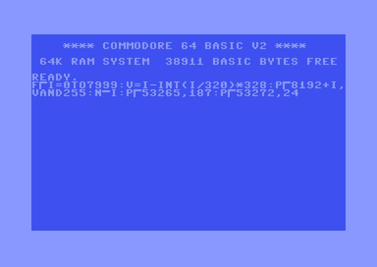 Startup screen with a BASIC snippet running. Startup screen with a BASIC snippet running. |
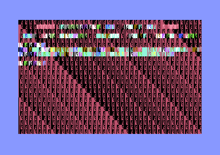 The same screen after switching to bitmap mode. The same screen after switching to bitmap mode. |
NUFLI, specifically, uses the above hires bitmap mode. Out of the box, this mode is limited to two colours per 8×8 block, an “ink” and a “paper”. Since the C64 has a fixed palette of 16 colours, one byte of colour data allows us to choose both freely for each block. For instance, the space character with code $20 turns into red ink (colour 2) on black paper (colour 0).
One might think that it would be possible to get more colours in a block by changing the colour byte while the electron beam is in the process of displaying the row in question, but this doesn’t work on the C64. The reason is that due to bandwidth reasons the VIC-II chip has to store a copy of the 40 bytes of screen RAM that applies to the currently displayed row of blocks. Even worse, to make this copy, it needs to stop the CPU and take over the bus for 40 clock cycles (each clock cycle covers 8 pixels being displayed) so it can perform DMA. This happens on the first scanline of every block, and the C64 demoscene settled on the name “badline” for this phenomenon, since it costs precious CPU time.
It didn’t take very long for the scene to figure out how to get more colours in a block anyway. The key to many tricks is the hardware smooth scrolling feature of the VIC-II. It’s possible to define a pixel offset of up to 7 pixels both vertically and horizontally; to move the image any further the contents of the memory need to be moved. The logic for scanning out the blocks line by line and keeping track of where we are within a block is defined by a state machine the hardware implements. It turns out that the condition to trigger a badline is simply to set the smooth vertical scroll value such that a block should be starting on the current raster the electron beam is on. Depending on where the beam is horizontally within the line, the resulting effect can vary.
When we trigger a badline in the visible area of a block by modifying the vertical scroll position, it comes as a surprise to the VIC-II. First of all, it has to wait three clock cycles to give the CPU a chance to finish possible write operations. During these three cycles it sees values of $ff on the bus instead of screen RAM. In hires bitmap mode, this results in light grey ink on light grey paper in those blocks. Afterwards, it starts updating the rest of its buffer with the current contents of the RAM. Most importantly, it doesn’t reset the row index within the block. This trick is called Flexible Line Interpretation, i.e. FLI (sometimes pronounced “flee”).
For demonstration, I wrote a tiny program that waits until the middle of the 4th row of characters, changes some character colours, then adjusts the vertical scroll in the middle of the scanline to trigger a badline. As soon as the CPU resumes execution, it restores the colours and the scroll position so the process can repeat in the next frame. In text mode, the three-cycle wait manifests as three characters with code $ff (a checkerboard pattern in the default character set) and a colour that depends on the code following the trigger.
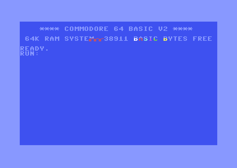 Triggering a badline in the middle of a row in text mode.
This means that we can easily get new bitmap colours on every single scanline, effectively shrinking the attribute blocks from 8×8 to 8×1 pixels. All we need to do is write two registers: update the base address for the screen RAM, then update the vertical scroll position at the right moment. Unfortunately there’s no way to prevent grey blocks on the left side of the screen, because trying to trigger the badline earlier will actually reset the block completely and repeat its contents from the beginning. The resulting 24-pixel wide grey area is often referred to as the FLI bug.
Here’s what happens if we modify the above program to trigger the badline too early, before it is time for the VIC-II to read the first character in the row:
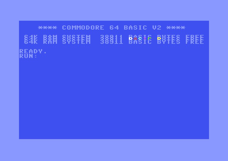 Triggering a badline in the left border, before the VIC-II starts reading the screen RAM. The current block is restarted as a result, then restarted again when the electron beam reaches the restored scroll position.
NUFLI uses an attribute block size of 8×2, i.e. it triggers FLI every second line, for reasons that should become clear in the following section. Here’s an example of what that looks like with a bitmap where each byte is just the row number from 0 to 199, and the paper colours are kept constant in each character column:
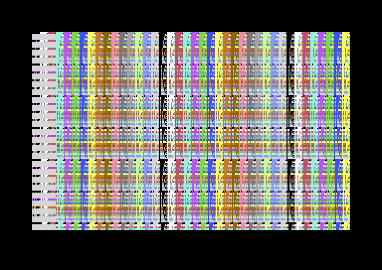 Test bitmap with 8×2-pixel colour blocks and visible FLI bug on the left side.
Since the first two scanlines of each 8-pixel section follow a normal badline, there’s no FLI bug, and we can see the bitmap’s own colours. The other three quarters of the block get their colours from the FLI that’s carefully triggered on the exact cycle the first block’s colours need to be read, so they are forced to be grey. The grey pixels are still somewhat usable, as we’ll see below.
Full-Screen Sprite Layers
While it’s nice to be able to increase the vertical colour resolution, having only two colours within every 8-pixel run is still quite limiting. This is where the hardware sprites of the C64 come into play.
The C64 has 8 hardware sprites. Each sprite is 24×21 pixels, so its image neatly fits into 63 bytes at one bit per pixel. Sprites can be reused – multiplexed – several times in the same frame by changing their Y coordinates after they started getting displayed, as long as the new Y value is below the bottom line of the active instance, i.e. at least 21 over the previous value. For instance, if we position a sprite with Y coordinate 100, then as soon as we’re on line 101 we can change its Y to 150, and the sprite will be shown in both positions – we can even reprogram it to have different colour and contents between the two instances. Unfortunately, they cannot be reused horizontally, so we can only ever display 8 sprites within a scanline (technically there’s a trick to show 9 sprites, but with severe limitations that make it impractical for anything other than a demonstration).
If we line up all sprites in a row, we can only cover 24×8, i.e. 192 pixels out of the 320. Fortunately, the C64 offers the ability to expand the sprites along both axes by doubling their pixels. Another useful feature of the hardware is to be able to control priority: sprites can be set to appear either in front of or behind the background, i.e. the ink layer of the bitmap. In this case, the latter option is more useful, so we use sprites as underlays. This is where the U in NUFLI comes from.
Sprite Configuration
NUFLI images use a very specific configuration of sprites to make sure that both the FLI bug and the main section benefit as much as possible. The last 8 pixels are limited to showing the rightmost column of the bitmap, as there’s no sprite left to cover them.
![]() NUFLI sprite configuration across each scanline. The numbers in parentheses are the physical sprite indices, which also act as hard-coded priority (0 being the topmost)
NUFLI sprite configuration across each scanline. The numbers in parentheses are the physical sprite indices, which also act as hard-coded priority (0 being the topmost)
Having two sprites in the FLI bug area more than makes up for the loss of useful bitmap layers, and we can still put grey ink pixels in front of the sprites. The lower priority sprite over the FLI bug is set to multicolour mode, which means that its horizontal resolution is halved, but we can use three colours instead of just one. Normally the extra two colours are shared among all sprites, but since all the other sprites are set to hires mode, in this case we get three additional independent colours, albeit at half the resolution.
 NUFLI layers in the FLI bug area, with thicker borders marking the colour blocks for each layer. The number of available colours is given per block, not including transparency.
The next 288 pixels of each row can use three colours in every 8×1 region: high-resolution ink in front of the low-resolution sprite-paper mix. They are not all independent from each other, since each sprite spans 48 pixels, or 6 blocks horizontally, but this is still a huge improvement for artistic freedom.
 NUFLI layers in the main area for each 48-pixel wide column covered by a single sprite. All marked blocks can only have one colour plus transparency.
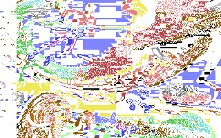
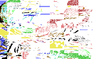
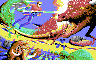
It’s difficult to picture how such a system works in the abstract, so let’s look at the layers of an existing NUFLI image. This is the Space Harrier title screen from the Game Art Beyond collection.
 Ink Ink |
|||
| → | |||
 Hires Hires |
 Low resolution sprites Low resolution sprites |
→ |  Final image Final image |
| → | |||
 Paper Paper |
Generally speaking, the ink layer is used to add fine detail, and the sprites blend the attribute block boundaries.
Covering the Whole Screen
NUFLI images have all the sprites expanded vertically to double size, but this doesn’t mean that they cannot use the full vertical resolution. This is thanks to the fact that the pointers that specify the address of the sprite’s contents are also located in the currently active screen RAM. When we change the address of the screen RAM, we not only change the colours of the bitmap, but also the sprite pointers, which are read afresh in every scanline. Since the address changes happen on even lines, while the sprite rows advance on odd lines, every scanline gets a unique combination.
Normally, in order to fill the whole screen with Y-expanded sprites, we need to move each one of them downwards three times in the visible area. We can set up the top row during initialisation, then as soon as it starts showing, we can change its Y coordinates before reaching the top of the image. This way we can cover up to 83 scanlines (i.e. 42×2-1) out of the 200 without having to use CPU time over the visible background, then advance the Y coordinates by 42 for each following row.
The way NUFLI images are set up, the background spans rasters 48-247. This is a necessity because the video chip cannot generate badlines outside this region. It’s also important to know that sprites with Y coordinate N start showing on scanline N+1 due to the way they’re implemented in hardware. The table below shows a possible schedule for covering all 200 background lines by only having to update Y coordinates three times within the area of the image. Also, the timing of those moves is completely flexible, they can be done anywhere within the respective intervals.
| Raster | Action | Sprite Instance | Background |
|---|---|---|---|
| 0-46 | Move sprites to Y = 46 | ||
| 47 | Move sprites to Y = 88 | 1st | |
| 48-88 | 1st | Rows 0-40 | |
| 89-130 | Move sprites to Y = 130 | 2nd | Rows 41-82 |
| 131-172 | Move sprites to Y = 172 | 3rd | Rows 83-124 |
| 173-214 | Move sprites to Y = 214 | 4th | Rows 125-166 |
| 215-247 | 5th | Rows 167-199 | |
| 248-256 | 5th | ||
| 257- |
The NUFLI implementation leverages another esoteric bug in the VIC-II called sprite crunching. In a nutshell, by toggling Y-expansion just at the right time the video hardware can be tricked into messing up the current sprite offsets that normally advance by 3 bytes per scanline. This causes the sprite to be displayed three times in a row with different offsets, because the hardware is looking for byte offset 63 to conclude the sprite, which it misses due to the misaligned position, and the 6-bit counter wraps around twice before the process ends.
![]() The famous Commodore balloon sprite shown normally and crunched on its third row. The byte with the alternating bit pattern (chosen for demonstration purposes) would never be visible without exploiting this bug in the hardware.
The famous Commodore balloon sprite shown normally and crunched on its third row. The byte with the alternating bit pattern (chosen for demonstration purposes) would never be visible without exploiting this bug in the hardware.
In the case of NUFLI, the scrambled sprites cover the first 123 scanlines, and with the additional move during the initialisation we get 165 rows for free in total. Since at this point we have only 35 rows left, we can cover the full screen with sprites by updating each of them only once within the visible area! We just have to make sure that they are all moved before reaching the end of background row 164 (raster 212). All in all, this trick saves us 16 register updates for the Y positions, and we can use the time to update colours instead.
This is how the sprite update schedule works specifically in NUFLI:
| Raster | Action | Sprite Instance | Background |
|---|---|---|---|
| 41 | Trigger first raster interrupt | ||
| 43 | Timing stabilised, move sprites to Y = 43 | ||
| 44 | Set inital sprite colours | 1st | |
| 45 | Move sprites to Y = 170 | 1st | |
| 46 | Crunch sprites on their 3rd line | 1st | |
| 47 | 1st, crunched | ||
| 48-170 | 1st, crunched | Rows 0-122 | |
| 171-212 | Move sprites to Y = 212 | 2nd | Rows 123-164 |
| 213-247 | 3rd | Rows 165-199 | |
| 248-254 | 3rd | ||
| 255- |
All that’s left to unlock the full power of NUFLI is to update the colours of the sprites as we present the picture line by line.
Timing and CPU Budget
To understand the limitations and the possibilities, we need to take a closer look at how the video hardware interacts with the CPU. The C64 comes in two flavours supporting major video standards: PAL and NTSC. While there are a few variations in the oldest models, in practice we can assume the following timings:
| Standard | Cycles per Second | Number of Scanlines | Cycles per Scanline | Cycles per Frame | Frames per Second |
|---|---|---|---|---|---|
| PAL | 985248 | 312 | 63 | 19656 | 50.12 |
| NTSC | 1022727 | 263 | 65 | 17095 | 59.83 |
Since PAL machines get slightly less cycles per scanline, they are more constrained in how much processing they can do between badlines. Therefore we need to build the system for PAL first, and later we can adapt it for NTSC.
Refreshing the bitmap colours is not the only thing that steals CPU time. Every active sprite needs two cycles on every scanline it spans so the video hardware can look up its pointer, and read the three bytes to display on the upcoming line. Sprite DMA takes place in the side border area. Since we have all 8 sprites active throughout the whole screen, there’s basically no time left for the CPU to run when there’s a badline.
Let’s look at the breakdown of what happens in each cycle of a scanline on a PAL system in various scenarios relevant to NUFLI. The regions with yellow background are data transfers from RAM to the video hardware, while the grey ones are the three-cycle wait periods where the VIC-II gives the CPU a chance to finish any pending write cycles. In the case of NUFLI there’s really only one write cycle that could be potentially clawed back, which I marked with a ✏️.
 Scanline cycle breakdown on a PAL system. Each cycle corresponds to 8 pixels, i.e. one attribute block. The screen area is between cycles 17-56, and generally we can see 4 cycles worth (32 pixels) of border area on the sides. The cycles marked “Blank” are normally outside the physical display area, but otherwise they behave identically to the visible border. The sprite fetches on the right border are for the next row.
Every block consists of 8 scanlines. The first one is a normal badline, while the 3rd, 5th and 7th ones are FLI lines. The initial badline leaves exactly one cycle for the CPU in the whole scanline, so we can’t even run a single instruction to completion. As for FLI lines, they have 4 CPU cycles available, which are taken up by exactly one 4-cycle instruction: the write to the vertical scroll register. The moment the write happens is marked by ❌, and the CPU stops in the next cycle.
It turns out that with all sprites enabled it is impossible to perform FLI on every line over the full 40-block width of the screen! There’s simply no time to perform the necessary steps: updating the screen RAM address, then updating the vertical scroll, since these operations would normally take 12 cycles altogether, and we’re missing 8. In other words, we’d need to limit the number of active sprites to 4. Or, if we are galaxy brain demosceners, we can play sudoku with some undocumented instructions of the 6510 CPU, and do it with 6 sprites. And, by the way, we’d still need to find time to update the Y positions to be able to cover the bottom section of the screen.
Since we’re forced to leave every other scanline with the same bitmap colours, we get at least 44 clock cycles to play with in each two-line section. It takes 6 cycles to write an arbitrary value to an arbitrary location: 2 cycles to store the value in a CPU register, then 4 cycles to write it. Consequently, we can perform 7 updates (not counting the three FLI triggers). One of these is needed for modifying the screen RAM address, so we really only get 6 updates. We have a few cycles to spare, which is used to squeeze in an early update to the vertical scroll register at the end, so the next block can start with a normal badline again.
NUFLI images contain a table that specifies 6×101 register update slots, one byte for each. The reason it’s 101 and not 100 is because the first row of the table contains the initial values of the 6 wide underlays (the initial values of the FLI bug colours come from another location). These are the possible values:
| Value | Description |
|---|---|
| $0x | Set the colour of the underlay corresponding to the table column to x |
| $1x | Update the Y coordinate of sprite x for the last section of the screen |
| $2x | Set the border colour to x |
| $5x | Set FLI bug multicolour sprite colour 1 to x |
| $6x | Set FLI bug multicolour sprite colour 2 to x |
| $7x | Set FLI bug hires sprite colour to x |
| $ex | Set FLI bug multicolour sprite colour 3 to x |
When the image display routine is executed, the program uses this table to generate the FLI code on the fly. The generated code is slightly different depending on whether the machine is PAL or NTSC, thereby supporting both with a single executable. The code is very simple in structure, it just unconditionally writes VIC-II registers for the whole duration of the screen with the correct timing.
Due to the way the code generator works, values of $8x–$dx also have an effect: they set the colour of the underlay given by the high nybble minus 7 to x, i.e. $8x updates the colour of the leftmost underlay column regardless of which slot of the table it is in, $9x updates the second column etc. However, this is undocumented behaviour and probably never used.
In every row, the updates are performed in the order specified by the table. The timing of the code is set up such that the nth write precedes the nth underlay column, so colour updates always happen on time. Unfortunately, this leads to a very unpleasant property of NUFLI: the colour updates of the underlays are not in sync with the bitmap’s, because they are done on the second line of each bitmap colour block. This makes the format difficult to pixel in manually.
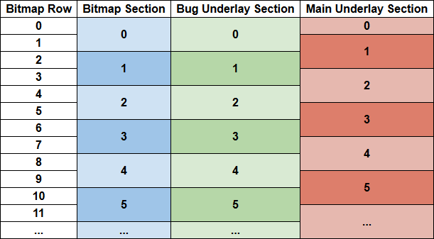 Colour update schedule in the different picture elements. The bitmap and the sprites covering the FLI bug are in sync, but the underlays in the main area are updated with an offset of one scanline.
It is possible to reorganise the colour updates such that 5 of the 6 underlay columns would actually be aligned with the bitmap (the rightmost one is problematic, because it overlaps with the CPU getting stopped for sprite DMA), but this alternative option got largely forgotten over time due to never having been properly implemented. The justification for the current setup (see post #8 in this thread) is that it allows the artist to have two different sprite colours within the same bitmap colour block, which can be useful sometimes, and of course it’s more regular than one with an odd column.
Conversion Process
NUFLI images are never created by hand from scratch. Instead, the general workflow is to convert an image to NUFLI using Mufflon, then optionally fix the most glaring issues by hand using the NUFLI Editor, which runs on the C64 itself. The fact that such an editor could be squeezed into the C64’s constraints is nothing short of a miracle!
The converter starts by preparing the image, so that it’s limited to the C64’s palette and resolution. The conversion consists of three main phases:
- Determine the best bitmap and sprite colours to replicate the image with the least error.
- Compute the register update table to realise those colour choices as closely as possible.
- Generate the bitmap and sprite patterns given the final colours such that the error is minimised.
It’s not possible to perform all the potential colour updates that the scheme would theoretically allow. These are the potential register updates within a section:
- 6 main section underlay colours
- 4 bug underlay colours
On top of that, we need to find the time to update the Y coordinates of each sprite once. As for border colours, the converter doesn’t support them, they are only possible to add in the editor by hand. But still, if we want to update 10 colours in a section, that just cannot happen, and something’s got to give.
Since the main area of the picture is the most important, the converter prioritises the 6 underlay columns. Broken down in a bit more detail, the high-level steps are the following:
- Determine the best sprite and bitmap colours for the 288-pixel main section with the X-expanded underlays.
- Build the table and mark its free slots. A slot is free when there’s no colour update required for a given column in a given section.
- Determine the best sprite and bitmap colours for the 24-pixel FLI bug section, limiting the possible sprite colour changes based on the number of free table slots in any given section. Update slots as needed.
- Find 8 free slots for the sprite Y coordinate updates in the relevant part of the picture.
- Generate the bitmap and sprite patterns given the final colours as defined by the table.
Step 1 is performed top to bottom, each of the 6 columns in parallel. The system tries all sprite and bitmap colour combinations for each 48×1-pixel section of the first scanline and picks those that can approximate the input image the best. Then it moves on to the second line, assumes that the bitmap colours stay the same and tries all the potential sprite colours to minimise error. Then it gets to row three, where the sprite colours of the previous row are kept, but new bitmap colours can be chosen. These odd-even rules are applied alternately until the last row of the picture.
Step 3 is also performed top to bottom, but two rows at a time, since the colours are aligned between the bitmap and the sprites. This is ensured by not allowing the FLI bug sprite colour changes to take place too early, so they are excluded from the first column’s table slots. The first section can be freely chosen, since its colours are set in the initialisation phase. Then for each additional section the system performs a brute force search of all possibilities that can be reached with the free slots of the update table in that row.
In practice, this scheme works nicely, and even the left edge of a image is fairly well reproduced, since usually there’s not that much going on there anyway.
NUFLIX
After dissecting a few NUFLI pictures, it became very clear to me that a lot of register update slots tend to go unused, because it’s really not necessary to change underlay colours that often. The sprite layer in the Space Harrier example above is quite typical in this regard. This realisation inspired me to ask the question: what if we allowed the main section underlays to potentially change their colour in every scanline? This would bring two crucial advantages:
- Artistic freedom: no need to fight the overlapping sections and play whack-a-mole with visual artifacts. If a sprite colour needs to be changed, it won’t affect its vertical neighbours. If some detail needs it, a colour can appear for even just a single scanline in the underlay.
- Independent blocks: every 48×2 block in the main section is now completely separate from its neighbours, so the search for the best colours can be fully parallelised and implemented on GPUs much more efficiently than before.
This question eventually led to the creation of NUFLIX. The main difference from NUFLI is that instead of building a table to generate code from, we generate the code itself ahead of time. Doing so allows us to be more flexible, since we can use the power of a modern computer to do the hard work.
Generalised Updates
NUFLIX has to work with the exact same CPU budget as NUFLI. However, it allows more potential updates in each section:
- 6×2 underlay colour updates in the main section, as each of them can change colour twice in every two-line block if needed
- 4 FLI bug colour updates
- 1 border colour update
Besides these, it also needs to deal with the sprite Y coordinates the same way as NUFLI. Now, it would be possible to emit fully NUFLI compliant images by exploiting the undocumented feature to update any sprite colour from any slot by using the $8x–$dx value range. The problem is that due to the hardwired timing of the generated code, we couldn’t handle a lot of combinations that would otherwise fit in the CPU time budget. Instead, I opted to generate more efficient code that takes advantage of identical values being set to different registers (e.g. changing several sprites to the same colour). In practice, we can often fit 8-9 updates in a section with this system.
Due to the more flexible nature of handling the register updates, the optimisation process is slightly different from NUFLI. Instead of dealing with the main area and the FLI bug in separate phases, everything is thrown into a bag and sorted out in a single pass. This includes not just the colour updates and the sprite Y positions, but also the two writes necessary for the FLI portion itself: changing the screen address and the vertical scroll position.
The overall conversion process consists of the following steps:
- Determine the best bitmap and sprite colours to replicate the image with the least error separately for each section (every 48×2 block in the main part and every 24×2 block over the FLI bug).
- Assign the colours of the FLI bug sprites to the four available slots in a way that minimises the amount of register updates necessary to realise it.
- Collect all the register updates needed to display the image. Every update includes a target address, a value and timing constraints.
- Generate the code that executes as many updates as possible such that all the timing constraints are respected. If not all updates fit in the time budget, use some heuristics to skip the least important ones.
- Generate the bitmap and sprite patterns given the final colours such that the error is minimised.
- Deal with differences in video standards.
Let’s go through these steps in detail.
Finding the Best Colours
Allowing every sprite in the main section to change colour on every line means that each block of 48×2 pixels can be checked independently.
In each block we have two lines of sprites with 16 possible colours each, hence 16×16 = 256 possible combinations to check. For each combination we compute the choice of bitmap colours – 6 ink-paper combinations – that minimise the error with respect to the input image. We determine the error by assuming the chosen bitmap and sprite colours, then trying all the 7 possible patterns for every pair of pixels:
| Pixel 1 | Pixel 2 |
|---|---|
| Paper | Paper |
| Paper | Ink |
| Ink | Paper |
| Ink | Ink |
| Sprite | Sprite |
| Sprite | Ink |
| Ink | Sprite |
In other words, we cannot combine the sprite and the paper colours within any pair of pixels, we have to choose either one or the other. Fortunately the bitmap colours can be evaluated independently for each of the 6 blocks, because the errors are additive.
All told, this boils down to a bunch of straightforward nested loops: 256 sprite colours × 6 attribute blocks × 256 bitmap colours × 8 pixel pairs × 7 patterns. Given that there are 6×100 sections in the main area, the innermost loop has to go through over 13 billion iterations.
This is the most time-consuming step in the whole conversion process, but thanks to the fact that the NUFLIX converter implements it as a compute shader, it can run in a split second for the whole image. The actual implementation runs in two phases: first it generates the results for the 256 sprite combinations in parallel for every block, i.e. the error metrics and the best bitmap colours that go with them, then it picks out the lowest error option for each block.
We can do the same for the FLI bug area, but the parameters are different. Each independent block is 24×2 pixels, and the unknowns we’re looking for are the four sprite colours to replicate the block as closely as possible. While bitmap colours can be freely chosen in every 4th section, I decided to make things simpler by assuming light grey ink and paper everywhere. The four colours are not independent in this case: the hires sprite layer can be anything but light grey (no point in using that for sprites as we can use ink for those pixels), while the multicolor slots should have no repeated colours, as that would be a waste. So there are 15×14×13×12 combinations to check. Another difference is that for each pixel pair we can choose one of three “background” colours and each pixel can also be the ink or the hires sprite. This adds up to 19 different two-pixel patterns to test.
Finally, when choosing the best picks for each block, we should give preference to any option that avoids the use of the sprite layer, because that leaves us with less time pressure during code generation.
Pre-Optimising Bug Slots
The raw optimisation step gives us up to four sprite colours for each section of the FLI bug. However, when building the final output, we have to assign these to concrete registers. The NUFLIX optimiser implements a simple algorithm that shuffles the colours with the aim to minimise the necessary register updates during execution:
- Assign the colours to the 4 slots such that any common colours between subsequent sections are kept in the same slots. New colours prefer to replace the old ones that are the last to be used again (if ever) going downwards.
- Fill out the unused slots with whatever colour is going to be needed next in that slot, but flag them as not yet needed. Slots like this can be updated with very flexible timings.
- Rearrange slots so if there’s a colour swap between the hires and one of the multicolour slots, then make sure that the same multicolour slot inherits the previous hires colour. This is a very typical scenario, and it allows us to drop two register updates in one go without introducing too much error when needed.
- Use bitmap colours where available to get rid of rapid changes in sprite colours where possible. The benefits of this step tend to be marginal, but every little bit counts.
- To conclude, repeat step 2.
Let’s work through an example image to see what this looks like in practice.
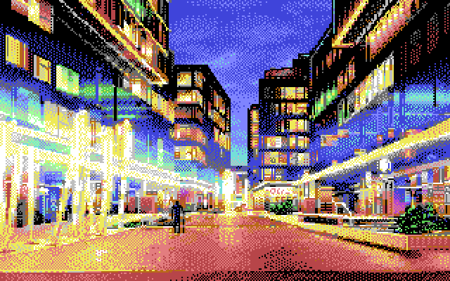 A screenshot from Area 5150 transformed into 320×200 C64 pixels from the original 640×200 CGA image.
Most images don’t have a lot of things going on at the edge so this is quite an extreme example! First we take the 24-pixel strip on the left and feed it into the compute shader to extract the optimal colours. Then we perform the five steps outlined above. The last image shows how we can reproduce the original from layers using the final colours (note that the light grey pixels come from the bitmap).
 Input Input |
→ |  Optimal Optimal |
→ |  Assigned Assigned |
→ |  Filled Filled |
→ |  Swaps Swaps |
→ |  Bitmap Bitmap |
→ |  Final Final |
→ |  Layers Layers |
The leftmost colour is always the hires sprite, and the other slots define the multicolour entries. Unused entries are marked with a striped pattern. Note that the hires slot is left untouched, since none of these transformations can affect the picture. The purpose of this step is to make it more likely that all the necessary colour changes will fit in our time budget.
Scheduling Register Updates
Before discussing the code generation process, let’s look at individual updates and their timing constraints.
When changing the colour of some element, we need to avoid the time when it’s being displayed. For instance, column 3 is displayed between cycles 32-37, therefore we either need to change it before cycle 32, so we see the effect already on the current line – which is always odd when our code runs –, or after cycle 37, so it only takes effect on the next line.
 Timing constraints for each possible register update in a NUFLIX image.
The ❗ marks the moment where we update column 6 to change colour on an even row. It’s one cycle too early, but the CPU is not available in the next cycle due to sprite DMA. As a result, the colours of the even line spill onto the preceding odd line for the last 8 pixels. Since this happens only near the edge of the image, it’s still useful to allow as an option.
The FLI trigger write is marked by ❌, and we assume it to be on cycle 58 for scheduling purposes, which is in reality delayed by the sprite DMA to fall exactly on cycle 14 on the next raster. The goal is to generate code that pads out time until cycle 54 or 55 (the latter must be a write cycle) before emitting the trigger.
It’s easier to see what’s going on through an example. Let’s take a slice from the image and look at the register updates needed to display it on the C64.
 Rows 74-79 of the image after mapping to layers.
 Rows 74-79 of the low-resolution sprite layer.
This slice is 6 pixels tall, i.e. it includes three sections. We’ll look at just the register updates needed while the middle section is displayed. Note that the first scanline of each section is a badline, so our code can only execute during the second one (line 77). In this particular area of the picture the colours over the FLI bug area don’t need to be updated.
These are the colours of the underlay columns under the main area, the ones changing during the relevant section marked bold:
| Line | Column 1 | Column 2 | Column 3 | Column 4 | Column 5 | Column 6 |
|---|---|---|---|---|---|---|
| 76 | blue (6) | blue (6) | black (0) | red (2) | dark grey (11) | light blue (14) |
| 77 | blue (6) | blue (6) | black (0) | pink (10) | dark grey (11) | light blue (14) |
| 78 | dark grey (11) | blue (6) | black (0) | black (0) | black (0) | light blue (14) |
In this section we need to perform four colour updates plus the two updates needed for the FLI process. We order them by their final deadline, then by their first available cycle:
| Register | Value | Cycle Range | Effect |
|---|---|---|---|
| $d02b | $0a | 11-37 | Set column 4 to pink on this scanline (odd). |
| $d018 | $08 | 11-55 | Update the screen RAM address. Only affects the next line. |
| $d028 | $0b | 26-55 | Set column 1 to dark grey on the next scanline (even). |
| $d02b | $00 | 44-55 | Set column 4 to black on the next scanline (even). |
| $d02c | $00 | 50-55 | Set column 5 to black on the next scanline (even). |
| $d011 | $3e | “58” | Trigger FLI on cycle 14 of the next line. |
The code snippet that gets generated from this update schedule looks like this:
; At this point the CPU registers are set to the following values:
; a=$3c x=$0e y=$0a

          ; first cycle (write cycle)
sty $d02b ; 11 (14)
lda #$08  ; 15
sta $d018 ; 17 (20)
lda #$0b  ; 21
sta $d028 ; 23 (26)
lda #$00  ; 27
ldx #$3e  ; 29
ldy #$78  ; 31, note: preloaded for use in the next section
nop       ; 33
nop       ; 35
nop       ; 37
nop       ; 39
sta $d02b ; 41 (44)
nop       ; 45
sta $d02c ; 47 (50)
lda #$38  ; 51
nop       ; 53
; Sprite DMA starts here and stops the CPU up to cycle 10 on the next line
stx $d011 ; 11 (14)
Dealing with the Time Budget
I decided to distinguish between two kinds of updates: immediate and deferred. Immediate updates are required to be performed on a specific scanline, while deferred updates can happen anywhere within a certain interval of scanlines. The distinction is not strictly necessary, but it made implementation easier for me. Examples of deferred updates are colours preceded by unused values for the same register, or sprite Y coordinates.
The code generation process starts by making lists of immediate updates needed for each of the 100 sections, and one global list of deferred updates in the order we’ll be needing them as we’re traversing the image top to bottom.
The final output of the code generator is a list of 100 snippets, one for each section. We generate these snippets in order from top to bottom by taking the immediate updates as input and trying to add as many of the currently relevant deferred updates as possible into the mix. If we run out of time while generating the current snippet, we remove an update from the input and try again. Every update is categorised by its priority, and the less important it is, the more likely it is to be removed. These are the categories in the order of increasing importance:
- Deferred updates that can be executed later.
- Deferred updates that expire on the current line.
- Bug colour swap between the hires and one of the multicolour slots. This implies moving the two updates to the next line.
- The single bug colour update that introduces as little error as possible is moved to the next line.
- A colour change in the main section whose top and bottom neighbours are identical, i.e. we can remove two updates while only affecting one 48×1-pixel area.
- One of the colour changes in a main section column that has two changes scheduled.
All other register updates, i.e. border colour changes and FLI related updates are exempt from this selection process. When we move a bug colour update to the next line, it becomes candidate for inclusion for the next snippet. If there’s already an update scheduled for the same slot on the next line, then we just drop it completely instead.
The NUFLIX editor provides feedback about the CPU time used for each snippet as well as any possible changes that were caused by dropped updates.
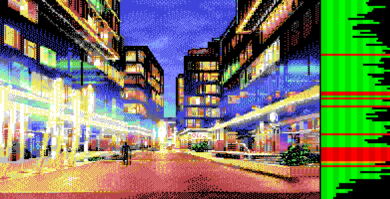 CPU cycles used per section, red and orange marking sections with dropped updates CPU cycles used per section, red and orange marking sections with dropped updates |
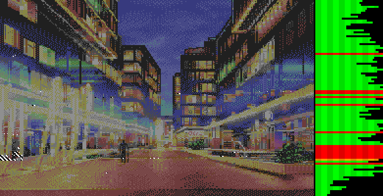 Pixels that changed due to dropped updates; the striped pattern animates in the editor Pixels that changed due to dropped updates; the striped pattern animates in the editor |
For instance, the above snippet from line 77 has 12 unused cycles, i.e. about 20% of the time still available. On the above images it’s roughly halfway between the first two red lines.
Assembling the Final Image
After we complete the code generation phase, we know for sure what colours we can use in the sprite layers. To account for any changes, we regenerate the bitmap and sprite layers with this knowledge in mind. If we’re converting an image, then we use that as a reference for the error metrics. On the other hand, if the layers are being directly edited, then we merge them and use the result as a reference image instead.
This is the point where we have to consider NTSC machines. NUFLI takes care of this by checking for the video standard during startup, and patching itself so the code generator emits slightly different instructions. In terms of timing, the difference between PAL and NTSC is that the latter adds a cycle before sprite DMA, and another one after. Altogether we get 4 extra cycles during each section (2 per scanline), but not all of them are necessarily additional. For instance, whenever we use cycle 55 for a last write in PAL, we don’t get an extra cycle in NTSC.
Taking everything into account, we can modify the PAL code by inserting delays of 1 to 4 cycles in it in various places. Since the fastest instructions take 2 cycles, the way to insert a single cycle is to change an instruction. For instance, an instruction that loads an immediate value into a register can be changed to load a value from the zero page instead. Also, instructions that write the A register can be changed into indexed writes, so they execute in 5 cycles instead of 4. The NUFLIX exporter makes a list of the necessary modifications and saves them into the file. Each modification is described with a single-byte command, and when the displayer routine detects an NTSC machine, it runs a small interpreter over these commands to rewrite the code in place.
Workflow Improvements
The original goal for this project was to improve the expressiveness of NUFLI, but something interesting happened along the way. Relaxing some of the constraints unlocked the possibility of speeding up the conversion process by orders of magnitude. With Mufflon, the best an artist can do is make some changes to the source image, re-run the converter, and wait at least several seconds to see how it turns out. NUFLIX makes this step basically instantaneous, and offers two additional features for a seamless experience:
- The tool can interface with a running instance of the VICE emulator through the binary monitor. After a connection is established, the results of every little change are instantly displayed inside the emulator.
- It’s possible to watch the input file for changes, and automatically trigger the conversion process when it happens. This allows the artist to work on the image in their preferred editor, and whenever they save, they can see how the final image will look within a fraction of a second.
Even better, when using the built-in editor for placing pixels, it’s possible to optimise the image incrementally. Used together with the VICE bridge, the feedback for the user is continuous, so it’s much easier to develop an intuition for the limitations imposed by the hardware. I’m reminded of Bret Victor’s famous talk, Inventing on Principle, which demonstrated with several examples how speeding up a workflow dramatically can result in a truly qualitative change in perception and lead to a whole new level of understanding. My hope is that NUFLIX will also help some artists in a similar manner.
Final Thoughts
NUFLIX is a nice improvement over what we had before, but it’s far from the ultimate solution. In the grand scheme of things, I had a fairly easy problem to solve, because brute force was a viable approach. The C64 video hardware has many features that could be combined in order to find the closest representation of an input image. For instance, we could switch both the bitmap or the sprite layers between hires and multicolour throughout the picture. We could allow different sprite configurations that adapt better to the image we’re trying to recreate. We can elect to perform FLI with a different cadence to free up the CPU. The problem is that many of these capabilities lead to non-local effects that would require a much more complex search algorithm to optimise.
There are two major directions this system could be developed further:
- Expand the algorithm to use as many of the hardware features as possible, and allow processing time to get arbitrarily long in order to find the best possible representation in an unsupervised manner. The final output of this algorithm wouldn’t be possible to fix manually, since it would rely heavily on the order of operations and a very specific memory layout.
- Add more options, but only as long as the tight feedback loop isn’t compromised. For instance, it would be straightforward to allow the artist to customise the sprite configuration depending on the needs of the piece they’re working on, or e.g. offer the ability to turn off FLI, which would both free up CPU capacity and prevent the grey bug. In short, this is the direction where we’d focus on building an interactive tool that offers a high level of control.
Both of these philosophies could lead to very interesting results and pose exciting technical challenges. With some luck, we won’t have to wait another 15 years for the next improvement. ;)